Full functionalities of Detail 3D (EN)
Introduction
Detail 3D is essentially an extension of the current established IDEA StatiCa Detail application. It adds a new Model type 3D and with this comes the implementation of a method for calculating stress fields in 3D space called 3D CSFM. Calculations and checks are implemented for the Ultimate Limit State.
Before going into the description of the functionalities of Detail 3D it will be good to point out the existence of Theoretical background, where you can read more technical details about the individual model entities and the calculations themselves.
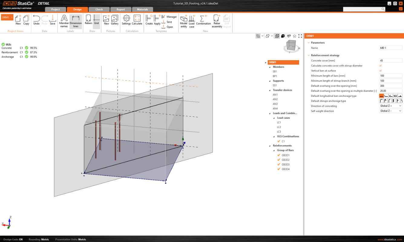
In the first step, the user can select a new Model type on the initial screen (in the wizard), where several templates are available, and of course, the option to enter a model from scratch.
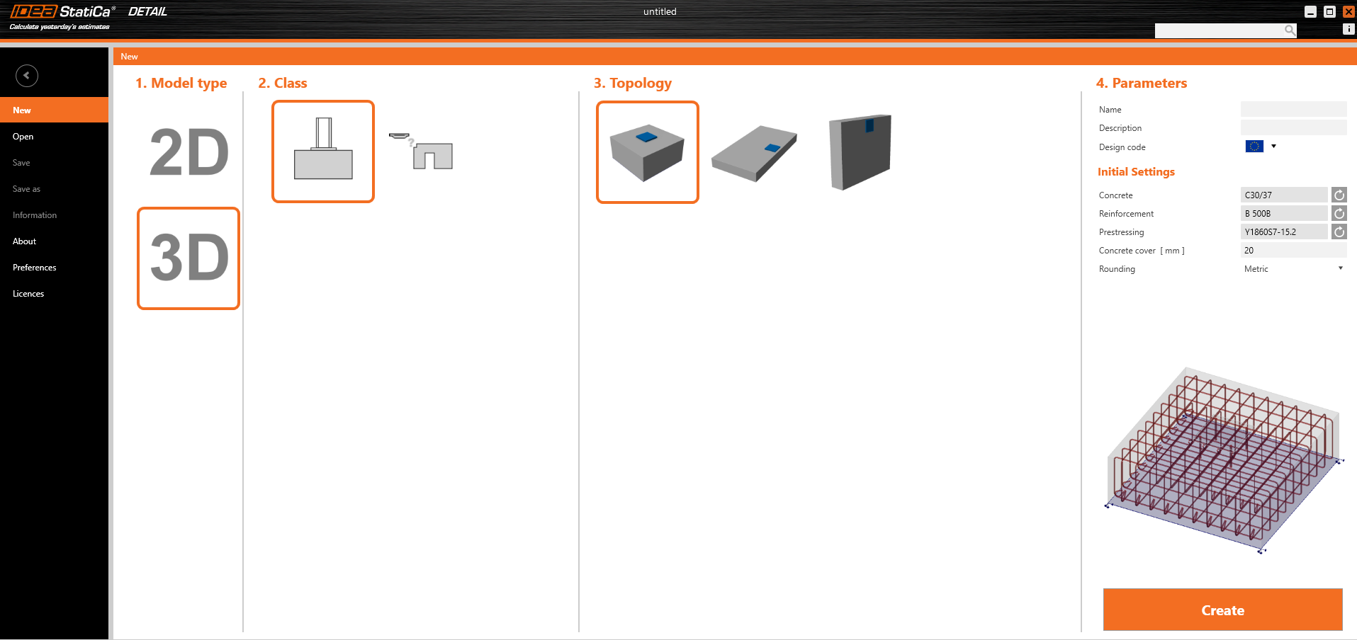
As for 2D models, you can edit the Initial settings in the right part, such as Design code, Materials, and Concrete cover.
After creating a blank model or a model from a template, options familiar to the 2D modeling environment are available.
Options for working with multiple Project items can be found in the top ribbon, as well as the now standard Undo/Redo buttons, Labels view options, Gallery controls, calculation settings, and template management controls.
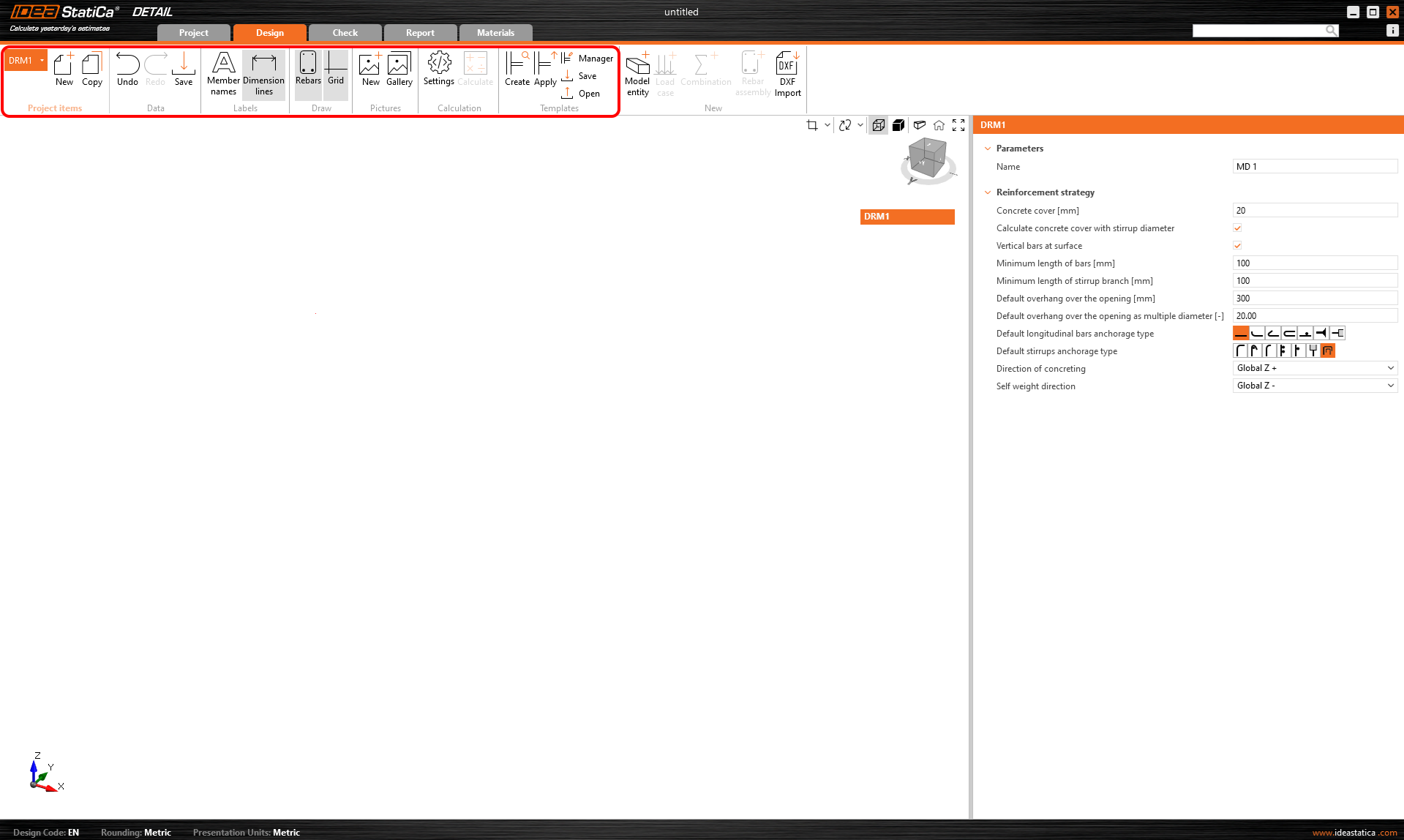
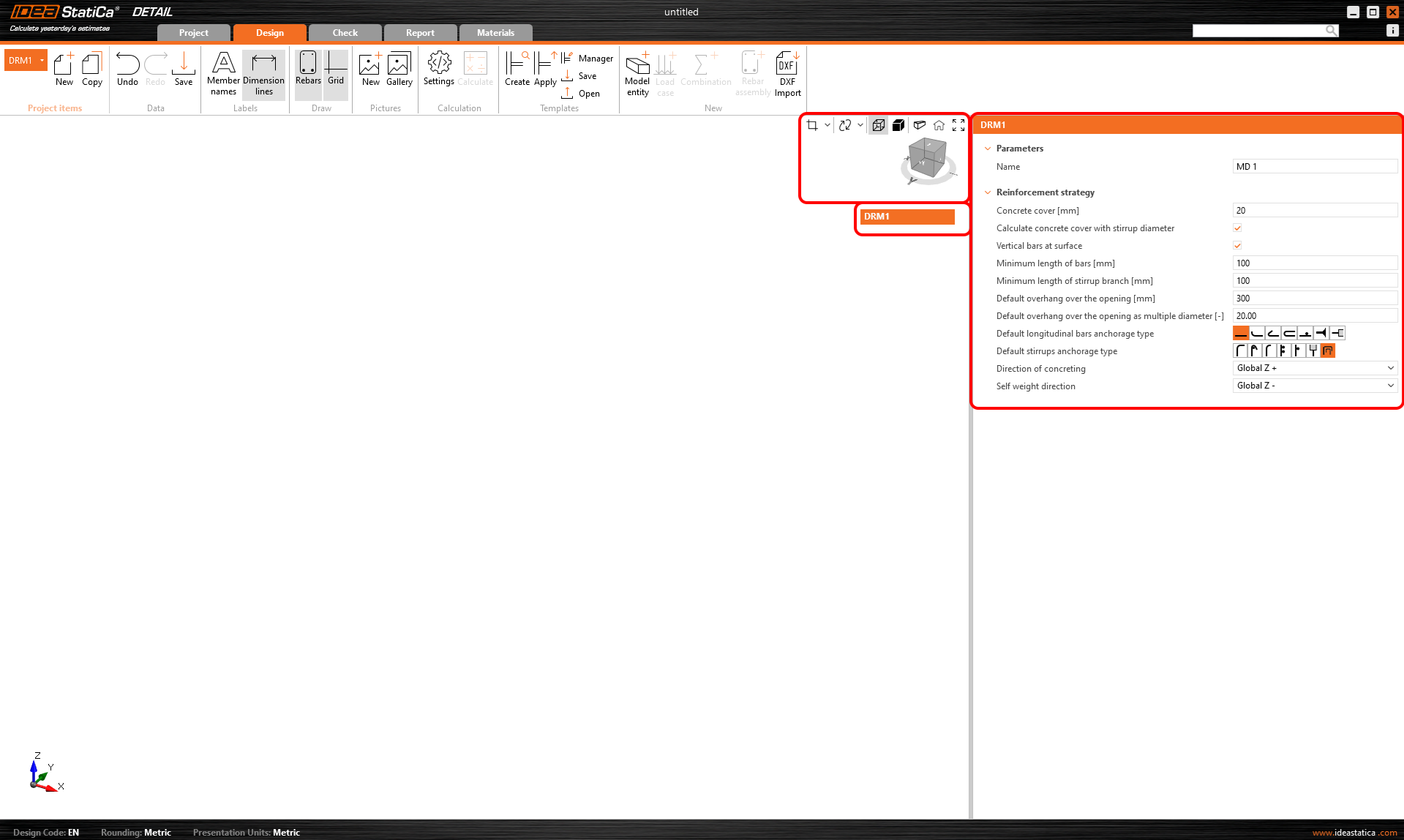
It also initializes the tree, whose first item, called by default DRM1, contains the default settings for the actual Project Item. Above the tree, you can find tools for manipulating the model.
Modelare
Entități Model
Includem următoarele în categoria entității Model în aplicația Detail:
- Elemente
- Reazeme
- Dispozitive de transfer al încărcărilor
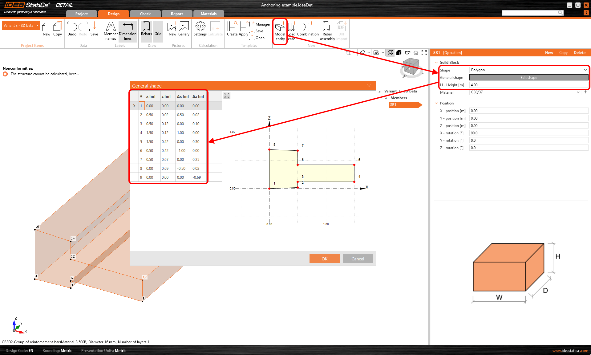
Poate fi introdus doar un singur Element, care poate fi definit ca formă Dreptunghiulară sau Poligonală. O formă dreptunghiulară este definită prin trei dimensiuni, iar pentru opțiunea Poligon, forma în spațiul 2D este introdusă într-un tabel folosind coordonate, care pot fi apoi extrase în spațiu. Pentru a defini forma generală a unui poligon, coordonatele individuale pot fi completate în tabel sau se poate utiliza funcția copiere-lipire dintr-un program de calcul tabelar (cum ar fi Microsoft Excel).
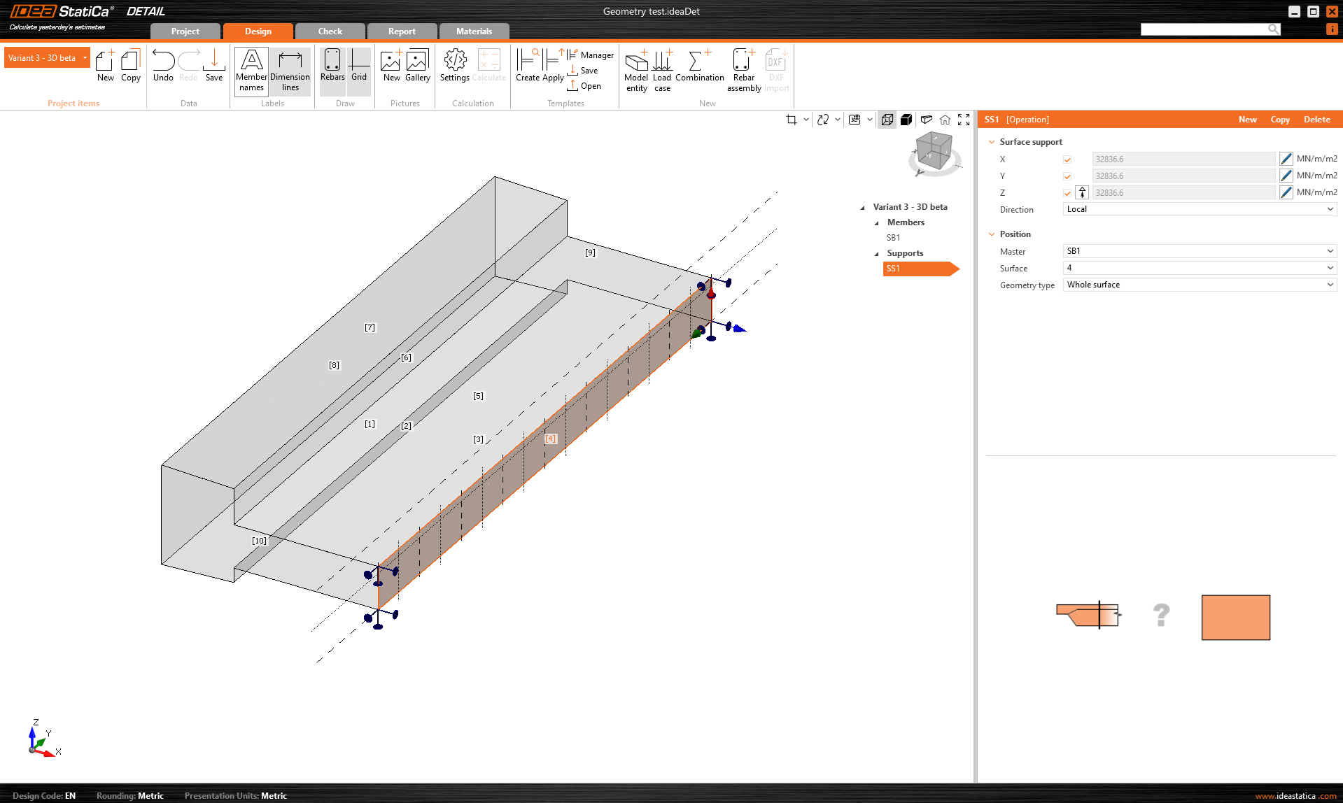
Rezemul de suprafață este utilizat pentru a susține modelul. Acest tip de reazem poate fi specificat în două moduri - două tipuri de Geometrie.
- Suprafață întreagă
- Polilinie
În ambele cazuri, trebuie să alegeți o suprafață de referință și, desigur, să definiți gradele de libertate. Rezemul poate fi definit ca elastic, iar tipul Numai compresiune poate fi utilizat pentru o direcție perpendiculară pe suprafața specificată. În figura următoare, putem vedea introducerea rezemului pe Suprafața întreagă numărul 4 și opțiunea Numai compresiune dezactivată.
Pentru a doua opțiune de introducere a poliliniei, același tabel este disponibil ca și pentru introducerea Elementelor. Din nou, puteți utiliza funcționalitatea copiere-lipire sau puteți introduce coordonatele manual. Forma introdusă poate fi deplasată de-a lungul suprafeței de referință folosind coordonatele X și Y sau rotită prin introducerea unui unghi.
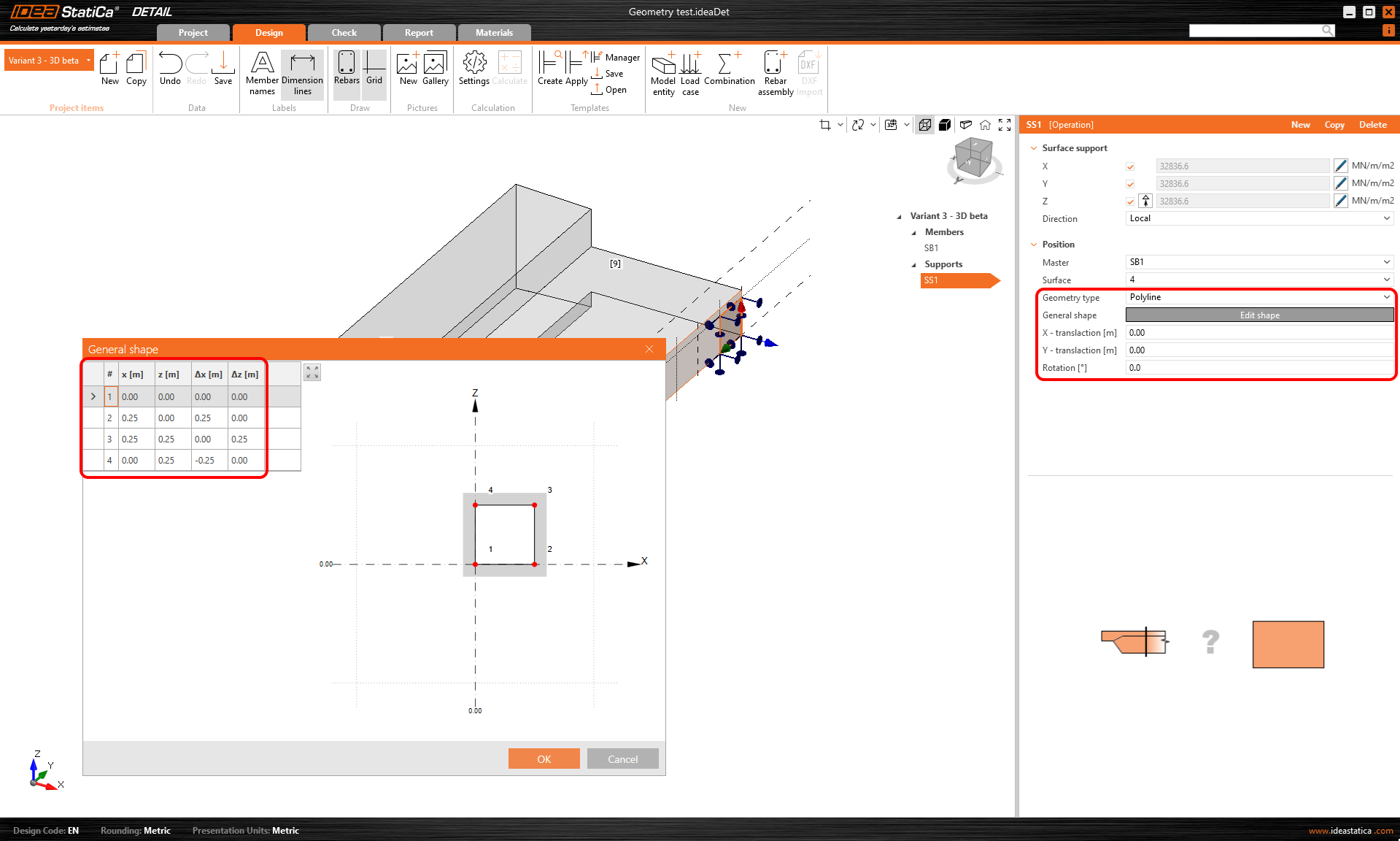
Rețineți că este posibil să specificați o polilinie astfel încât originea coordonatelor să fie la centrul de greutate al formei dorite. Poziția va fi apoi referențiată prin coordonatele X și Y față de acel centru de greutate.
Rigiditatea rezemelor pentru fundații
În timpul modelării, putem lua în considerare două cazuri. Dacă modelăm ancorarea la structură, rezemele pot fi considerate infinit rigide.
În cazul ancorării într-un bloc de fundație, rigiditatea trebuie definită corect. În plus, rezemele trebuie definite ca numai compresiune.
Valorile în direcția z (rigiditatea Kz) sunt preluate din literatură în funcție de tipul de sol corespunzător. Unexemplu specific poate fi găsit în tutorial.
Valorile depind de recomandările literaturii regionale relevante. Alternativ, valorile sunt obținute de la inginerul geotehnician.

În direcțiile orizontale (Kx și Ky), situația este mai puțin simplă. Recomandarea noastră generală este să se utilizeze o valoare de aproximativ 1/10 din Kz împreună cu raționamentul ingineresc.
O abordare mai precisă ar fi utilizarea unei proceduri iterative, din care am derivat recomandarea noastră.
Mai întâi, setați Kx și Ky la valori foarte mici (din motive de calcul, nu este recomandabil să setați valoarea direct la zero), de exemplu 0.1, și examinați tensiunile din armătură.

Deoarece aceste valori mici duc la deplasări nerealiste, rigiditatea ar trebui crescută treptat pentru a reflecta mai bine realitatea. Scopul este de a obține valori de deplasare mai realiste, menținând în același timp tensiunea de întindere din armătură la marginea inferioară aproape de valoarea inițială, cu o abatere mai mică de 5%.

Load transferring devices
Load transferring devices contain two entities the base plate and single anchor. Let's start with the Base plate. To specify the position, a reference surface and edge must be selected. These define the origin of the coordinates from which the X and Y distances are measured. There are two shape definition options, Rectangular and Polygon.
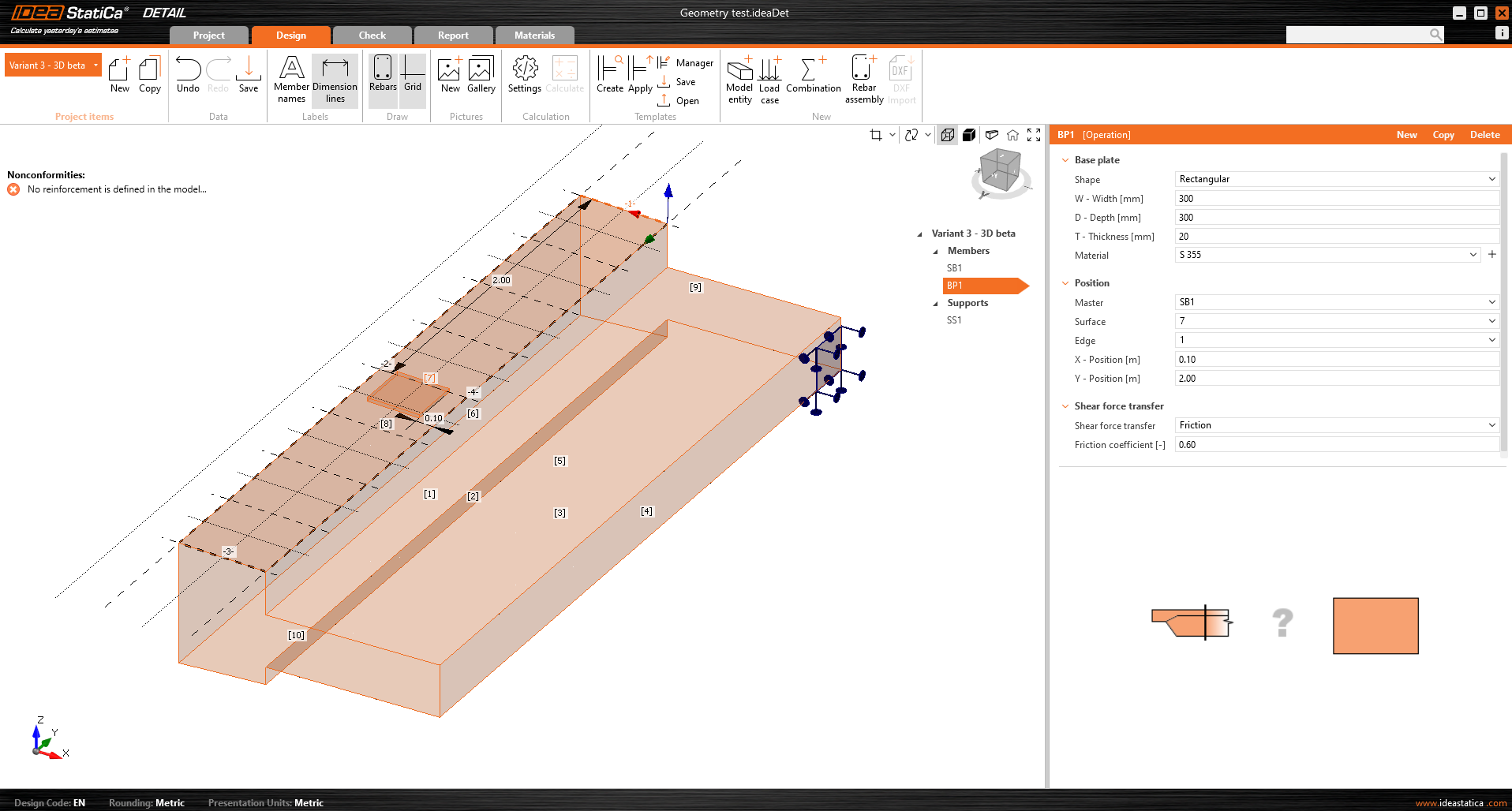
The base plate is connected to the concrete element by a contact that transfers compressive stresses and, if the user chooses, can also transmit shear stresses. There are three shear transfer mechanisms that can be selected:
- by friction
- by anchors
- by shear lug
The software does not allow you to combine these shear transfer mechanisms.
For the option by friction, the design value of the friction coefficient needs to be entered. For the option by shear lug, the steel profile, including geometry and position, needs to be inputted.
All the possible configuration of base plates can be found in the article: Base Plates Options.
The base plate can transmit either a point load or a group of forces. For a point load, the model can be loaded with six internal forces (Fx, Fy, Fz, Mx, My, and Mz) at any position on the base plate. For a group of forces, users can input the forces’ positions, intensities, and directions into a table, allowing for a general positioning on the base plate. It is important to mention that the base plate is point-loaded and doesn't have any stiffener or member welded on its upper face. Thus, for correct load distribution, it is important to use a relatively stiff base plate with relatively high thickness. Another option is to use Stub, that handless the issue with the plate stiffness.
A second load transfer device, the single anchor, can be added and interconnected with the base plate to create, for example, a base plate of the column anchored with four anchors (see the figure below). It is also possible to model separate anchors without a base plate.
More information about the interconnection with the base plate can be found in the Theoretical background.
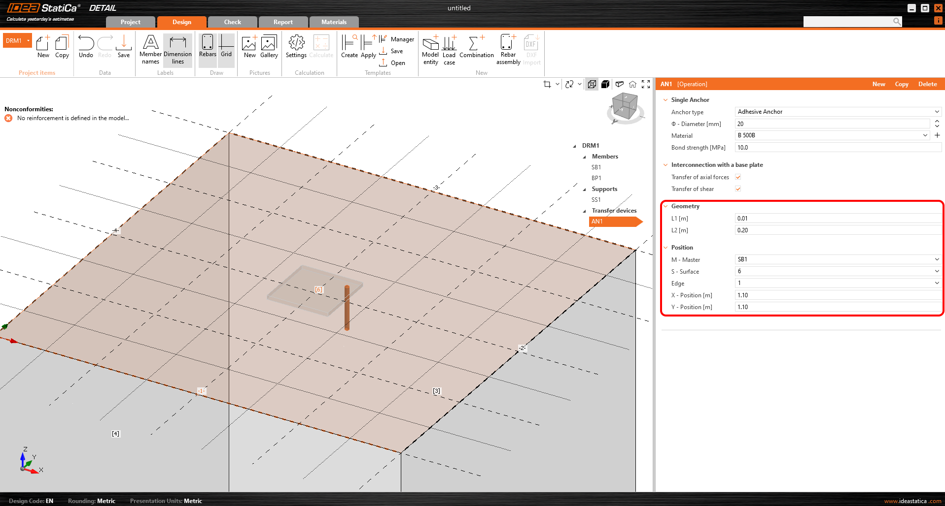
In terms of position and geometry, the anchors are referenced to the surface and edge of the block, including the determination of the relative position as with the base plate. Of course, it is possible to specify the length of the anchor in the concrete and the length above the concrete surface.
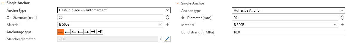
The anchors are implemented in two variants:
- Cast-in-place
- Adhesive anchors
For the Cast-in-place Reinforcement, the Bond strength is used according to EN 1992-1-1 chap. 8.4.2. In addition, it is possible to specify the Anchorage type for this type of anchor as for conventional reinforcement.
For Adhesive anchors, it is possible to directly input the bond strength, which the user can find out from the technical data sheet of the applied adhesive mortar. Note that it is necessary to input the design value of the bond strength. The following article will help you find the value.
See all anchors options in the article: Single Anchor Options
A thorough description of the behavior of the interconnection between the anchor and base plate is described in the Theoretical background.
Loading and combinations
Loading
Load cases can be defined in the same way as for 2D reinforced concrete elements. This means that each load case can be assigned either a Permanent or a Variable load type. The Permanent load cases are applied to the model first, and after a successful calculation, the Variable load cases are applied.
Type of load impulses
A total of 4 types of load pulses can be added to each load case.
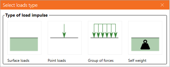
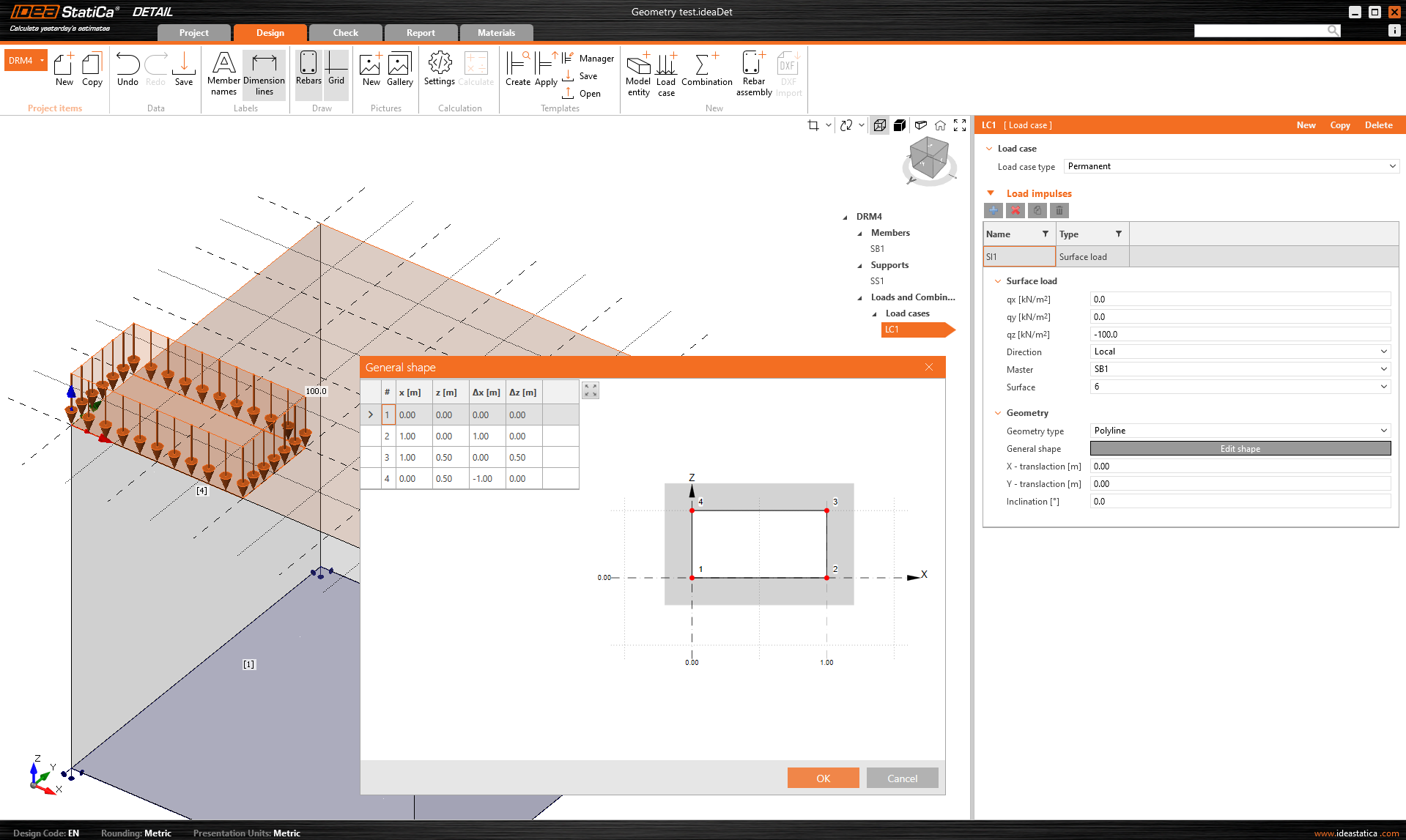
The definition of Surface loads is identical to the definition of Surface support. This means it is possible to specify it in two ways: Whole surface and Polyline. In the case of Surface loads, of course, the load intensity is entered in the three general directions.
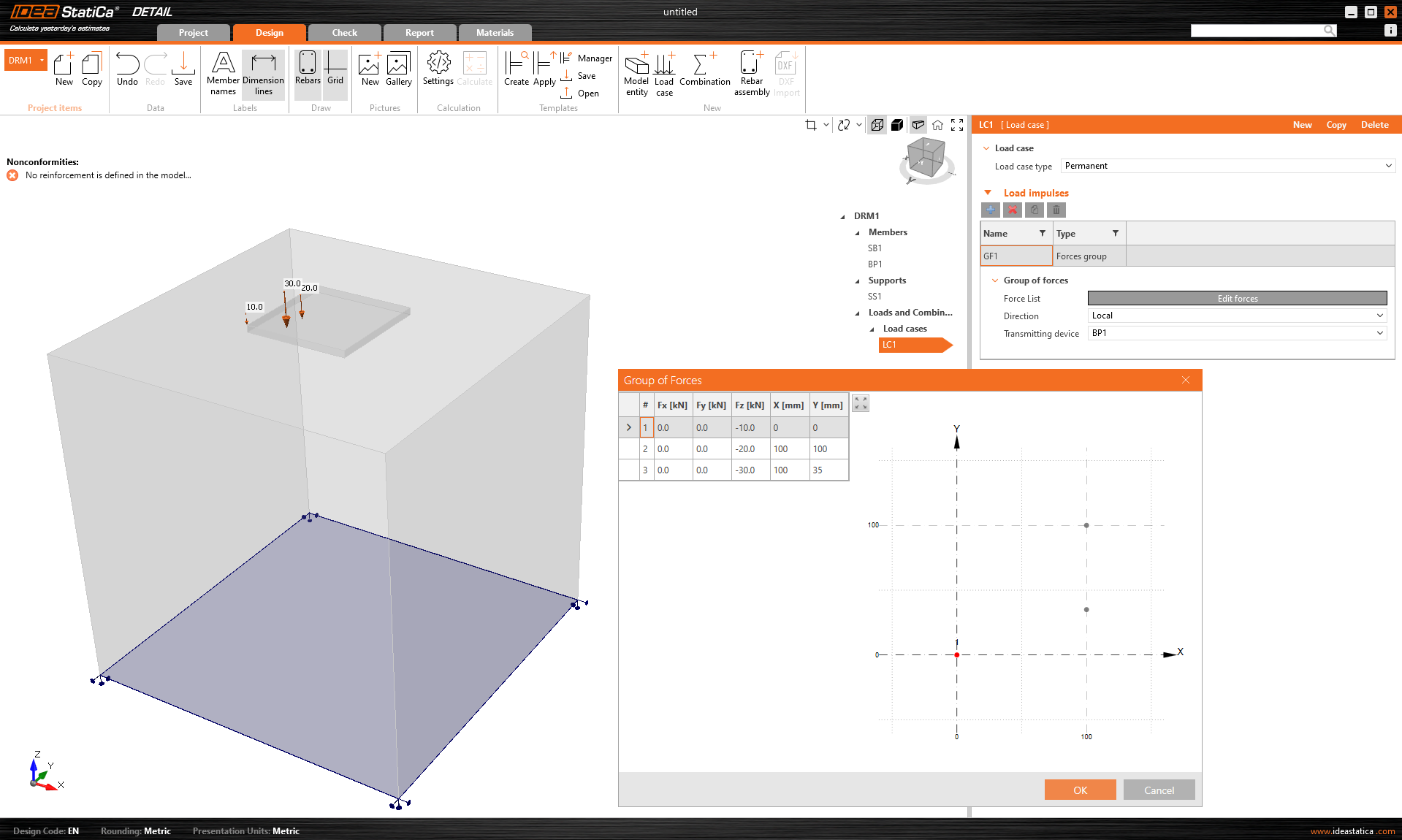
Group of forces is a load entity that allows you to specify forces in three directions anywhere on the model using a table. It can be referenced to the base plate or the surface of a concrete block. For tabular input, it is again possible to use the copy-paste functionality from the spreadsheet program.
The self-weight should be included in every model. For example, concrete foundations loaded with a bending moment will not so easily overturn.
Point loads can be loaded directly to the base plate with six internal forces Fx, Fy, Fz, Mx, My, and Mz in the general position.
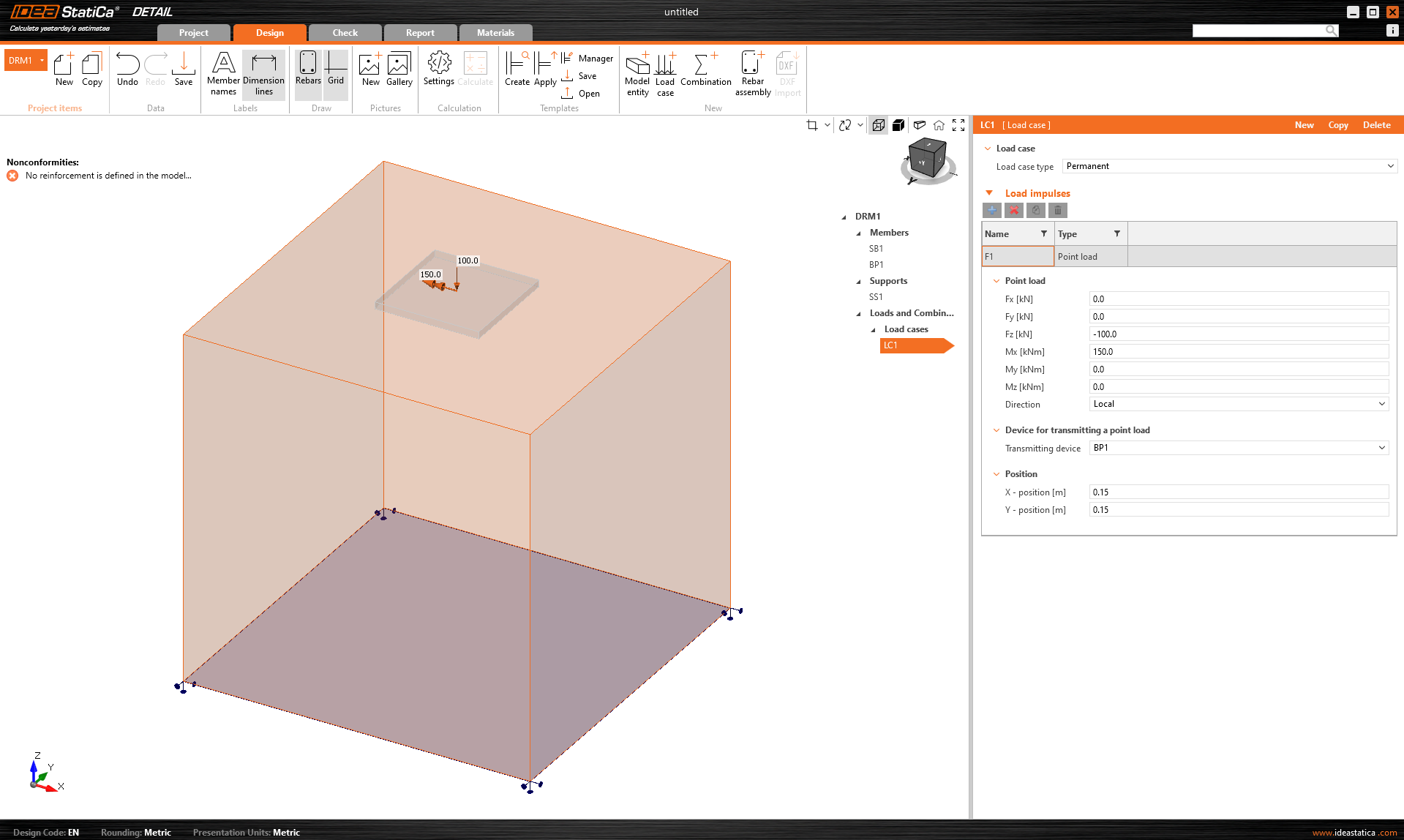
When using a base plate, applying this force directly to a realistic, deformable base plate can lead to unrealistic stress redistribution across the plate, anchors, and concrete. It is therefore more appropriate to use the second option - the stub.
The Stub
The stub is represented by a short part of the column above the base plate, which is modeled as a shell element structure and behaves as a physically accurate interface between the internal forces and the plate. A standard section database is used.

The 6-component internal force set (forces and moments) is applied at a single point on the bottom face of the stub - i.e. the base of the column.

Constraints transfer the forces to the top face of the stub, from where they are naturally redistributed through the stub into the base plate, anchors, and concrete.

This approach preserves the realistic stiffness interaction between column and plate and eliminates the need for any manual redistribution or artificial assumptions.
The stub was released in IDEA StatiCa version 25.1.
Combinations
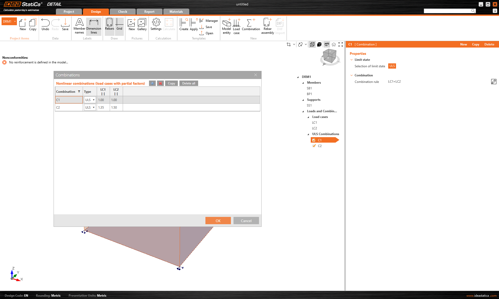
Because the analysis in IDEA StatiCa Detail is non-linear, so-called non-linear combinations are used. This means that individual load cases are not calculated and the results are not then added together. On the contrary, load cases of the same load type are added together before the calculation, of course with the respective coefficients defined in the combinations, and the individual combinations are then calculated. This is why the existence of at least one combination is a prerequisite for starting the calculation.
Only combinations for ULS can be defined.
Try out the new features of IDEA StatiCa today
Reinforcement
The model can be reinforced with Group of bars 3D. This reinforcement type contains many options, which we will go through in the following text. Thus, 4 types of Definitions of bar shape can be specified:
- By two points
- On surface edge
- On surface edge on more edges
- On polyline
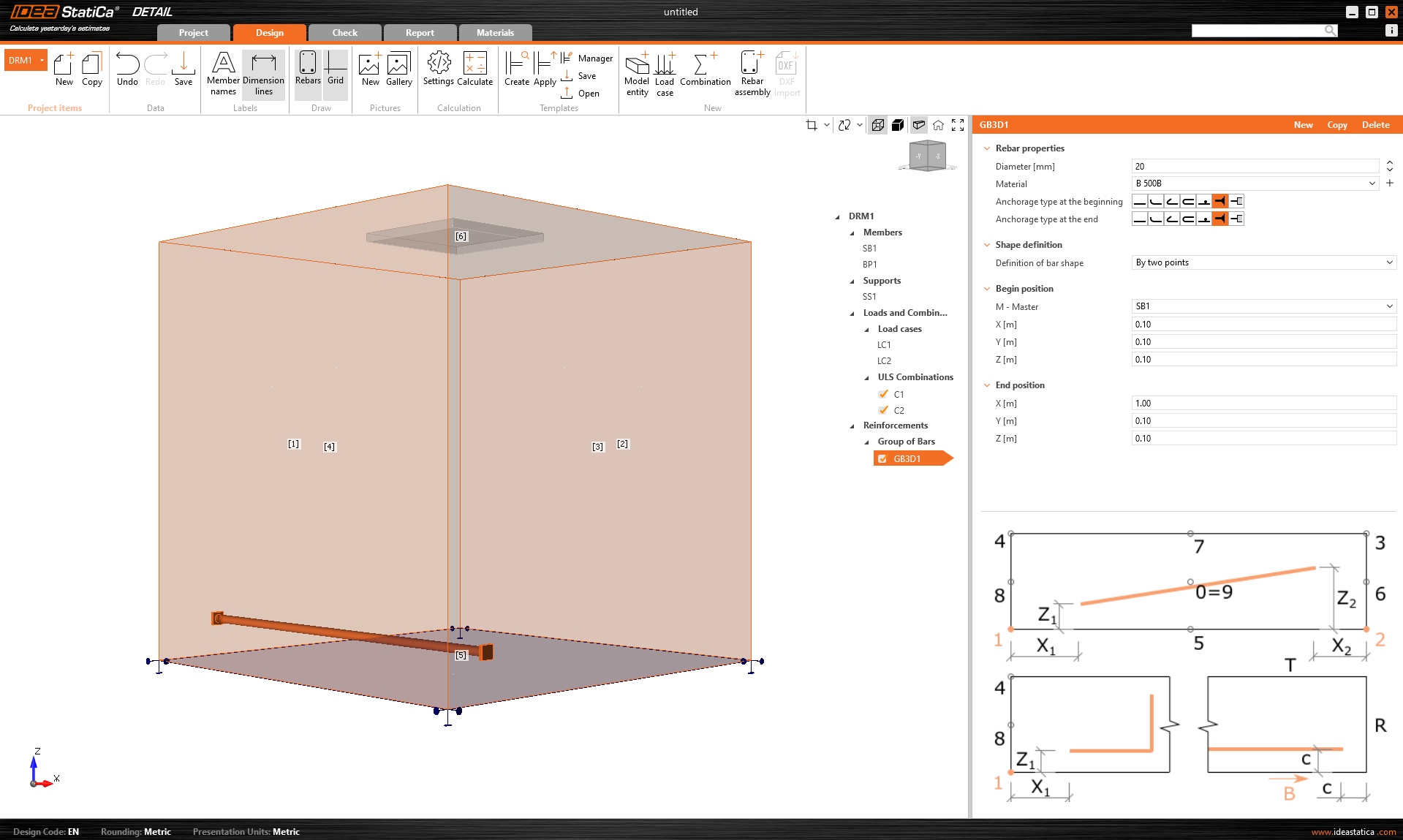
For each of these elements you can of course specify the diameter and material including the Anchorage type at the beginning and at the end of the bars.
Shape definition of the bar By two points is self-explanatory. You need to input two sets of cartesian coordinates X, Y, Z.
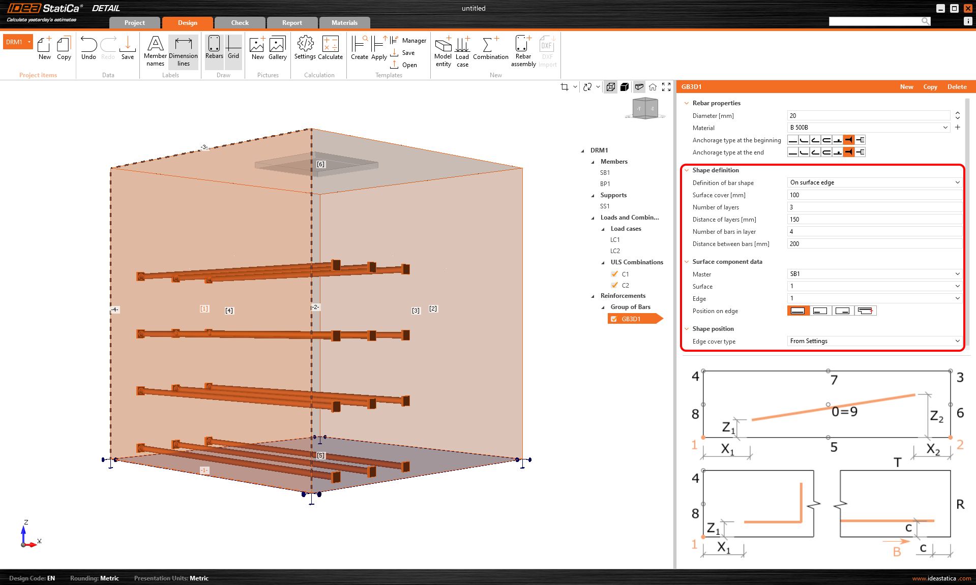
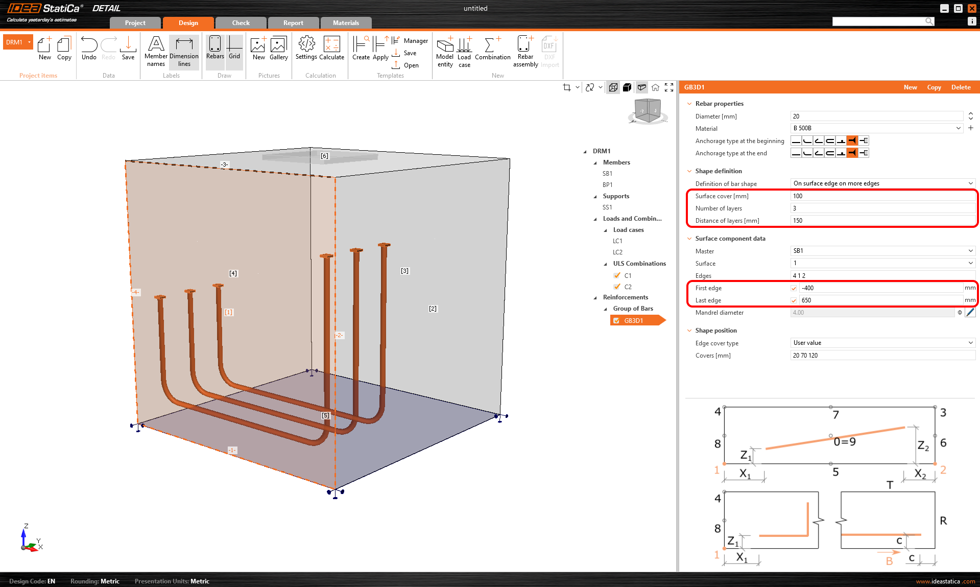
Definition On surface edge offers a lot of controls to position rebars to the required location. You can input reinforcement bars in more layers with more rebars in one layer with specified distances between bars in and between layers. Of course, it is also necessary to specify the reference surface and edge. Next, you must specify Surface cover, which defines the distance from the reference surface (from surface [1] in the figure below) and Edge cover, which defines the distance of the inserts from the side surfaces (from surfaces [4], [5], and [2] in the figure below), can be specified as From settings or User input. The default cover value (From settings) for the active Project item can be found in the first item of the tree (by default called DRM1) item of the tree. This was defined at the beginning of this article. The edge cover can be set as a unique value for each Group of bars.
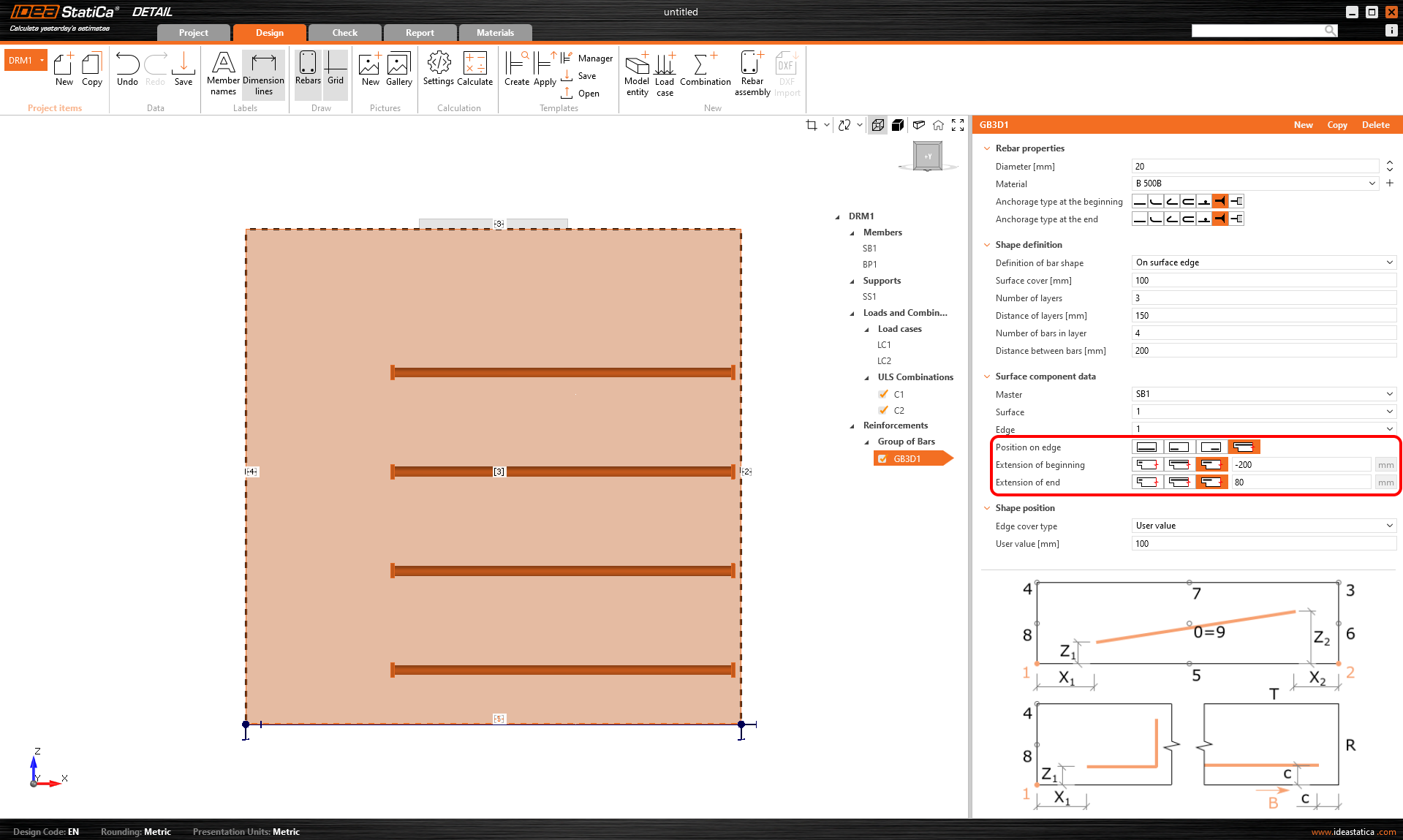
Lastly, Position on edge can be edited for this type of entry. For example, as shown in the figure below, it is possible to specify the reinforcement so that the User-defined Edge cover is applied only to the bottom surface [5]. The side surfaces are controlled by the Extension of the beginning and end.
Another type of definition is On surface endge on more edges. Here it is possible to specify a list of edges or surfaces on which the reinforcement will be placed, together with a list of cover layers for each surface as shown in the following figure.
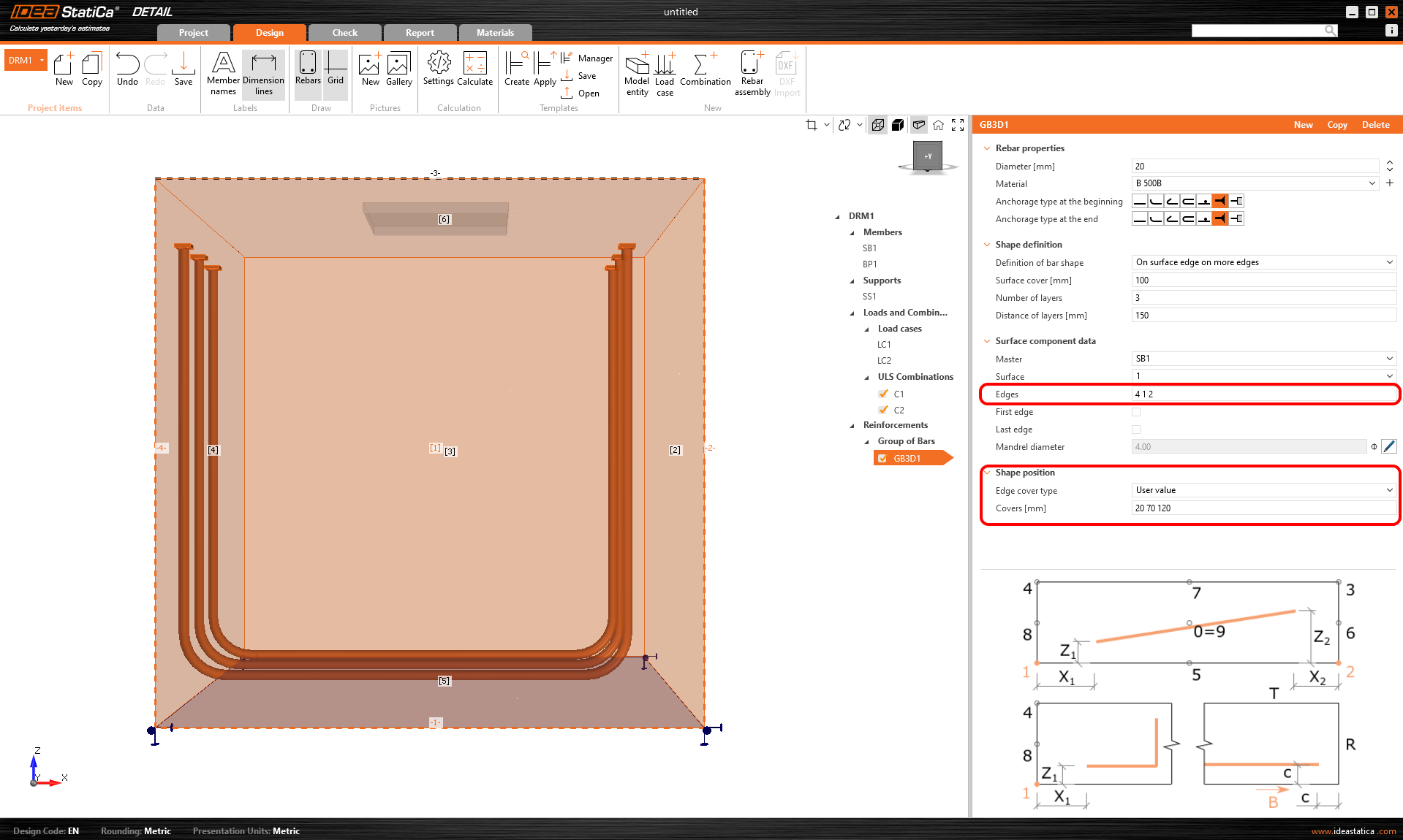
The cover can also be specified using the From settings option, as with the previous one. Again, it is possible to offset the reinforcement from the reference surface using the Surface cover and specify the Number and Distance of layers. It is also possible to lengthen or shorten the ends from the First edge and Last edge.
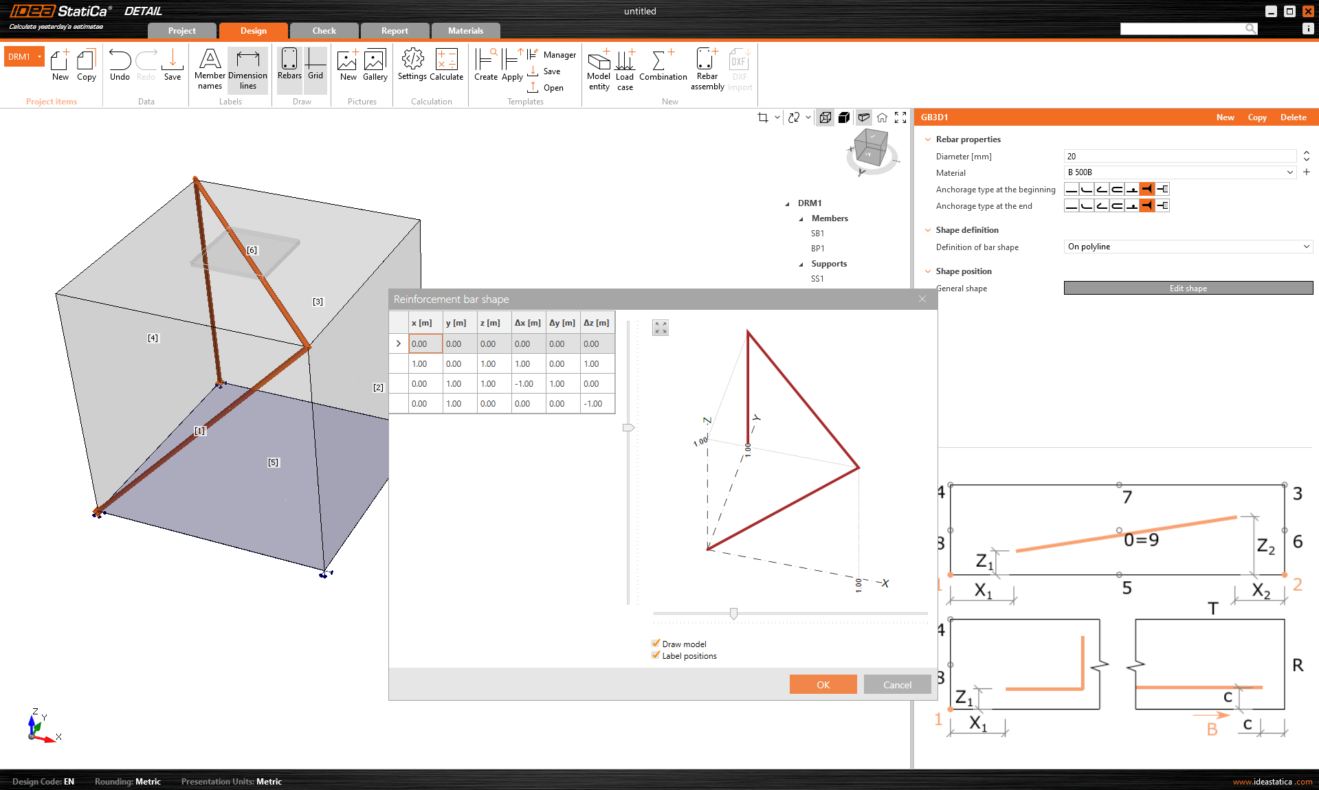
The last way of defining the reinforcement is On polyline. As in the model entities mentioned above, the reinforcement can be specified using a list of coordinates copied from a spreadsheet program. In this case, a 3D scene with the reinforcement displayed is additionally available for better orientation, allowing rotations around two axes.
Import of anchoring from Connection to Detail
Anchoring in a plain concrete block can be modeled and code-checked in IDEA StatiCa Connection. For certain cases, such as anchorage near the edge, the design is insufficient due to possible failure modes, and additional reinforcement is required. Although, this capability isn't available within the Connection app, it is possible to continue directly into the Detail application.
3D Detail is focused on solving anchoring into concrete blocks and analysis of both the anchoring elements and the concrete block itself. Moreover, a direct link is implemented between the Connection and Detail applications to simplify the process. Connection users who design anchoring according to Eurocode or AISC can import their model from Connection to the advanced 3D Detail by one button click.
- Import is allowed just for anchoring. If there is no concrete block in the Connection model, the export to Detail is disabled ("RC check").
- The model in Connection has to be calculated. If results are not available, the export icon ("RC check") is disabled. For export functionality, it is also necessary to have valid licenses for concrete applications. Otherwise, the export option will be disabled again.
- Only one concrete block for the import/export is allowed.
- Some anchor types are not supported for import, and we also do not recommend exporting so-called edge anchoring. A detailed breakdown of the limitations is provided in the article: Known Limitations for 3D Detail
The connection is imported, including
- The concrete block
- Anchors
- The base plates
- Loads
Additional information and parameters that are set according to the corresponding settings in the Connection:
- Shear transfer (through Anchors, Shear lugs, and Friction)
- Material
- Anchorage Type
- Anchorage type at the end
- Friction coefficient
The possible configurations and types of anchors that can be exported can be found in the following articles:
Export from Connection to Detail step by step
First, create a model of anchoring in Connection according to Eurocode/AISC and click the Calculate button.
When results exist, export of footing is enabled. By clicking the button "RC Check" in the ribbon, a dialog asking for the location and the name of the newly created Detail file appears.
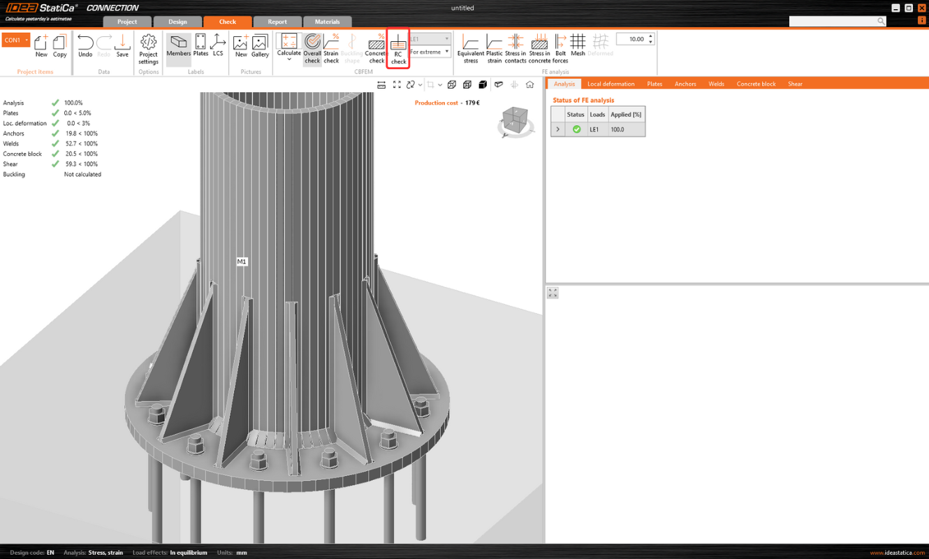
After a successful export, the project in Detail is created. The geometry of the concrete block and the base plate, the position and properties of anchors, and the load are automatically transferred to Detail. Surface support placed at the bottom surface of the concrete block is automatically created.
Note: It is only necessary to check the settings in the Z direction. (For foundation footings, we use compression-only with the soil stiffness setting; for a continuing structure, we can also enable tension support).
The most tricky part of this process is the import of the load. For every calculated load effect in Connection, the corresponding load case and the ULS combination are automatically created in Detail.
- The base plate is loaded by forces in welds, which are modeled as a Group of forces. For the loading of the base plate itself, the imported loading is represented by a group of forces following the stresses in welds between the base plate and steel members in the Connection model.

- Anchors are modeled and loaded independently from the base plate, and they are axially loaded by point loads. The loading of anchors is represented in the scene by a double of arrows in opposite directions. One arrow represents the tension force acting only on the top of the anchor. The other one represents the compression force acting on the base plate.

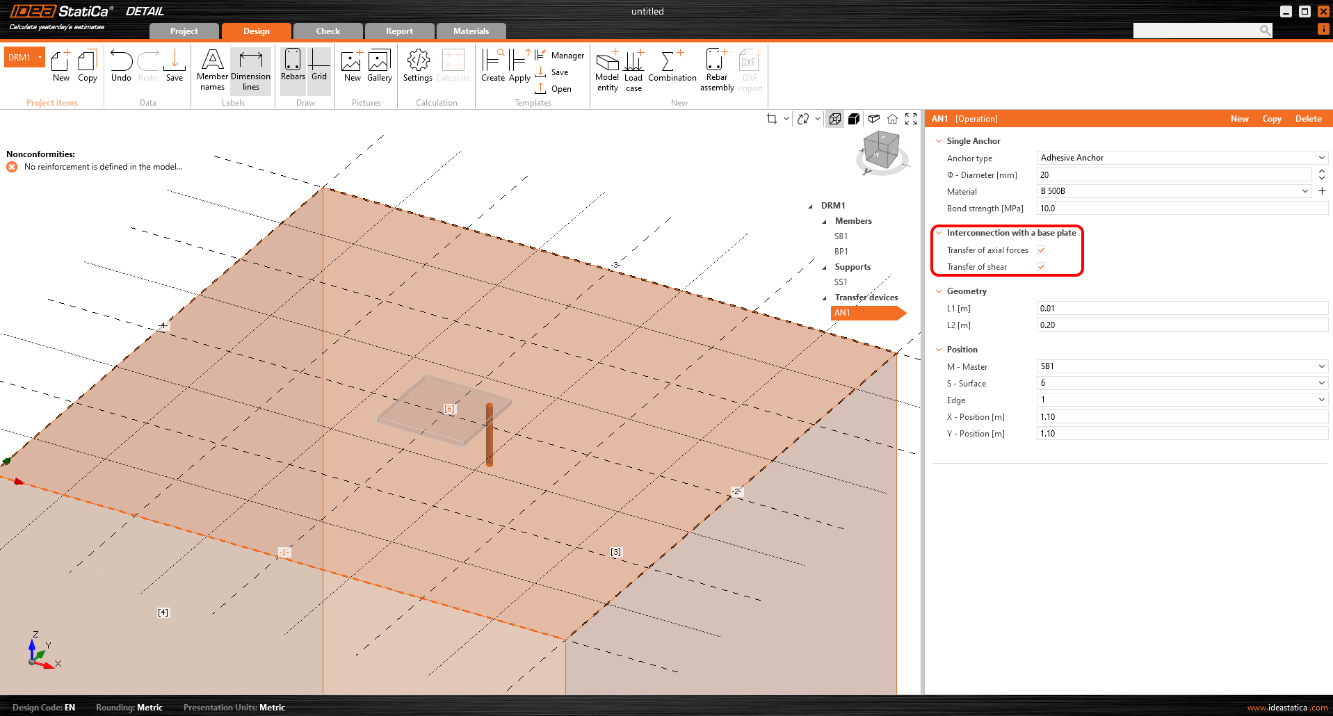
The Checkbox "Transfer of axial forces" is unticked by default as the anchors are loaded by forces directly.
Note: The following figure does not apply to cast-in plates, where axial force transfer is correctly checked after export. The reason for this can be found in the Theoretical Background.
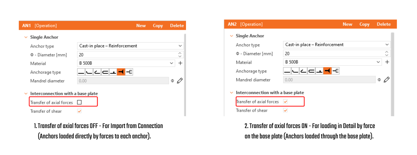
- Shear is transferred according to the setting in Connection by one of the options – anchors, shear lugs, or friction. If the shear force is transferred by anchors, you can turn off specific anchors by unticking the checkbox "Transfer of shear".
- If friction or shear lugs are set, shear in the anchors is never considered in the model. (Even if the checkbox is selected.)
Then just add the required reinforcement using the tools mentioned above and calculate the model. Don't forget set the Design Bond strength for adhesive(post-installed) anchors according to the manufacturer’s parameters.
It is also a good idea to check that the specified load will not overturn the concrete block. Overturning can be prevented by self-weight or sufficient compressive normal force. If the resultant vertical force is positive (the block will be lifted off the support), the calculation will also fail.
Since the concrete does not act in tension, the cover between the bottom reinforcement and the support will be peeled off.
A thorough explanation of imported forces acting on the base plate or anchors, which are shown in the figure below can be found in the Theoretical background.
Note: Released in IDEA StatiCa version 24.1. for EN. Gradually improved by implementing AISC, adding anchoring-element options, and refining the limitations. This article, including the full functionality, is applicable as of version 25.1.1. The individual changes can be seen in the release notes.
Try out the new features of IDEA StatiCa today
Results
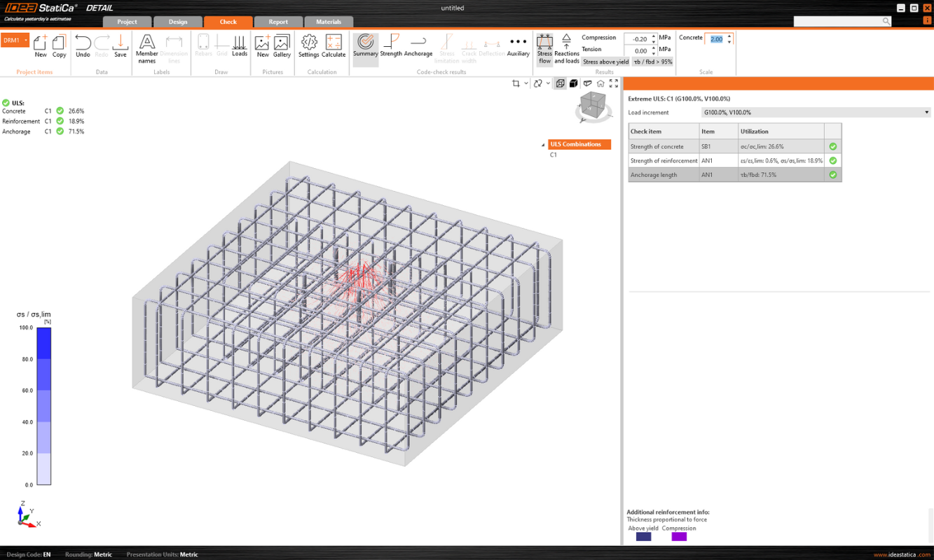
The display of the results is very similar to 2D Detail. However, there are some major differences, especially when it comes to results on concrete and results of anchors. In the following section, we will go through all the available results, focusing on the differences mentioned. In the check tab you can view a total of 4 types of results:
- Summary
- Strength
- Anchorage
- Auxiliary
Stress flow in Summary results shows you the vectors of compression principal stresses in concrete and utilization of the reinforcement and anchors to give you a basic overview.

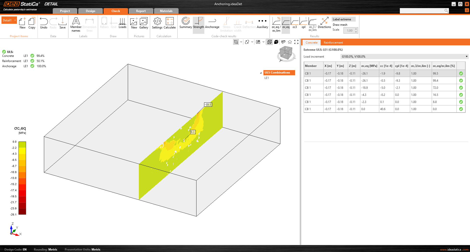
In the Strength check you can display the redistribution of stresses and strains for oncrete. In the top ribbon in the Results toolbar, you can control what will be displayed. It is also possible to display, the ratios σc,eq/σlim, and ε/εlim as well as the plastic strain, the level of triaxiality σc3/σlim, and the direction of principal stress for concrete. All results in the Strength are related to the Ultimate Limit State.
Note: You may notice that the Equivalent Principal stress σc,eq is zero just below the compressed base plate. Please read the Theoretical background where the σc,eq is defined. Or you can go through this verification article, where this phenomenon is explained and verified using a well-known tri-axial test: Tri-axial stress – the active confinement effect

Materials can be switched in properties.
The check for reinforcement is performed in a very similar way, where we again compare the limit values with the calculated stress/strain - σs/σlim, and εs/εlim.

For or anchors, we have two checks. One is the same as for reinforcement — comparing the limit values - σs/σlim, and εs/εlim.
Note: You may notice that each anchor is verified in several positions, which are automatically calculated as extreme cases.

In addition, we have Eurocode-based checks, which are done empirically according to the standard. The specific standard considered can be seen in the settings, where it is also possible to select a different one depending on the type of anchorage used, as well as the required standard based on regional practices.

Implemented codes: EN 1992-4, EN 1993-1-8, EN 1994-1-1

Anchorage check gives you information about bond stress and total force on the reinforcement and anchors.

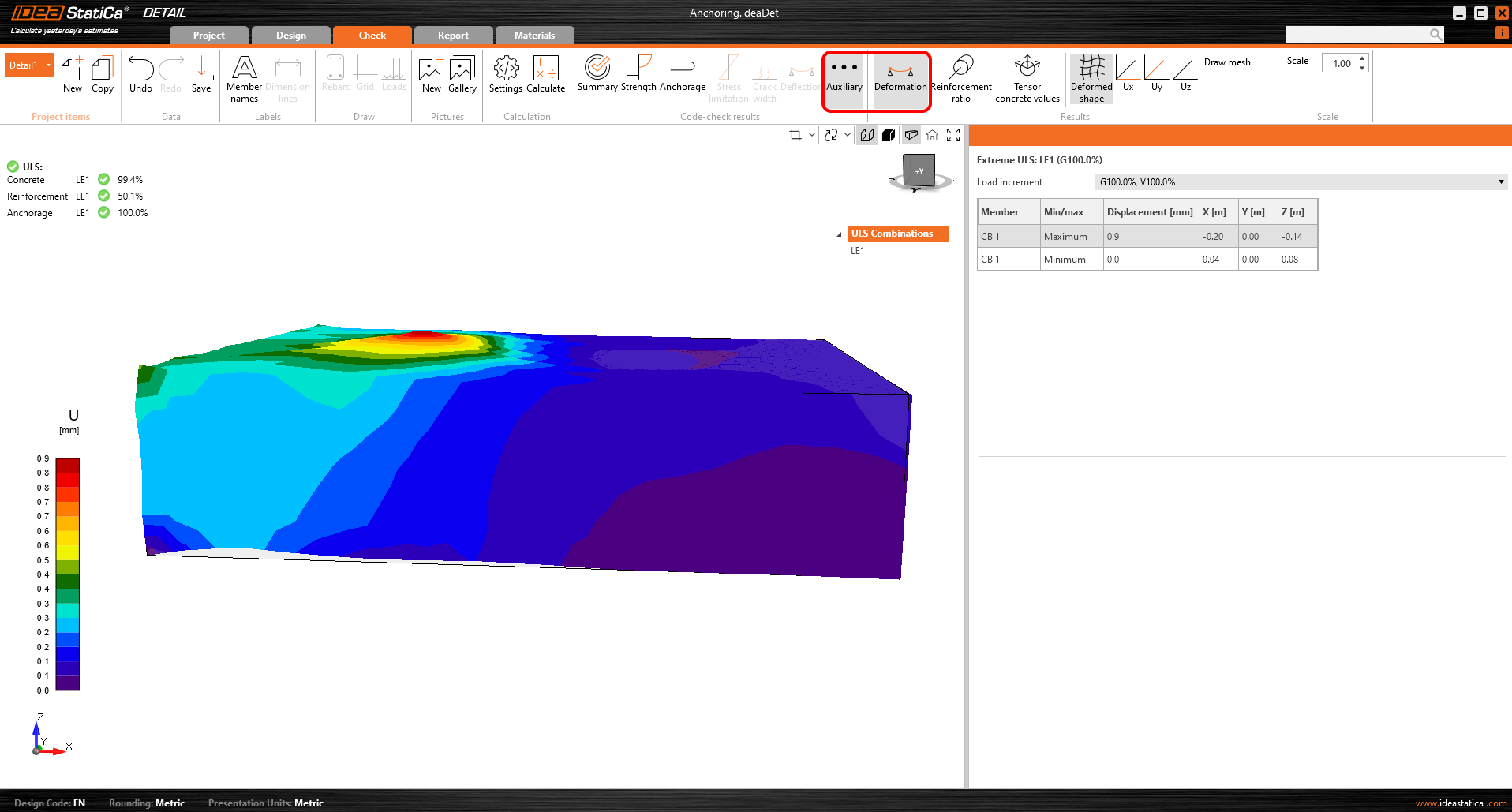
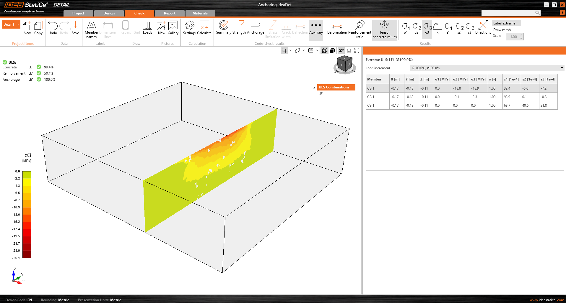
Last but not least, you can view the Auxiliary results in the application - Deformation, Reinforcement ratio, and Tensor concrete values. The first type, Deformation, can display scaled deformations of the ULS non-linear model.
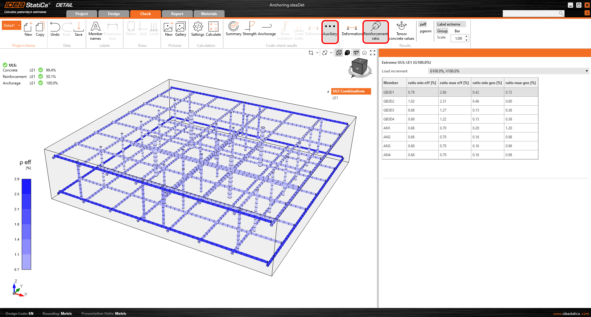
The Reinforcement ratio shows the values used to compute the Tension stiffening effect.
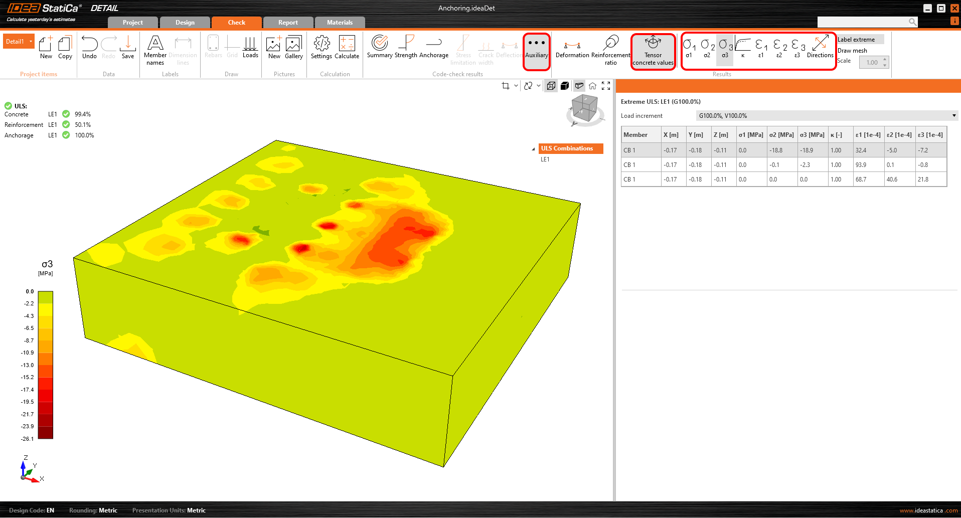
Tensor concrete values allow you to display the intensities of principal stresses in concrete and their direction.
The result sections can also be used.
Investigate model behavior with Section results and Stress check
Section Results allow insight into the stresses within the concrete element. It is possible to create any number of sections and in any plane.
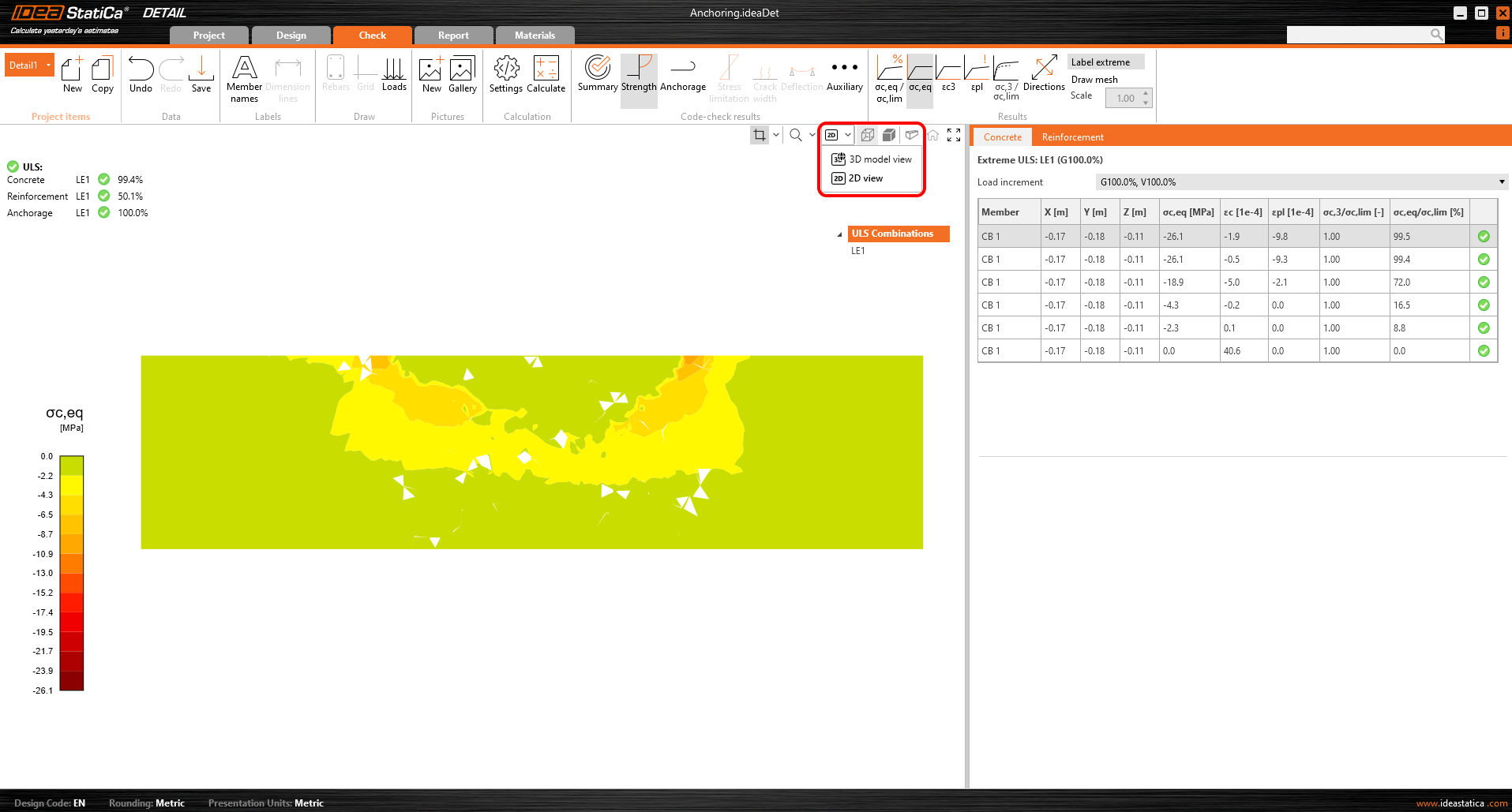
For 3D models, there is an option for displaying results for concrete - Section results. To define or modify the sections, you need to use the section button in the view control, which is in the top right corner of the scene.
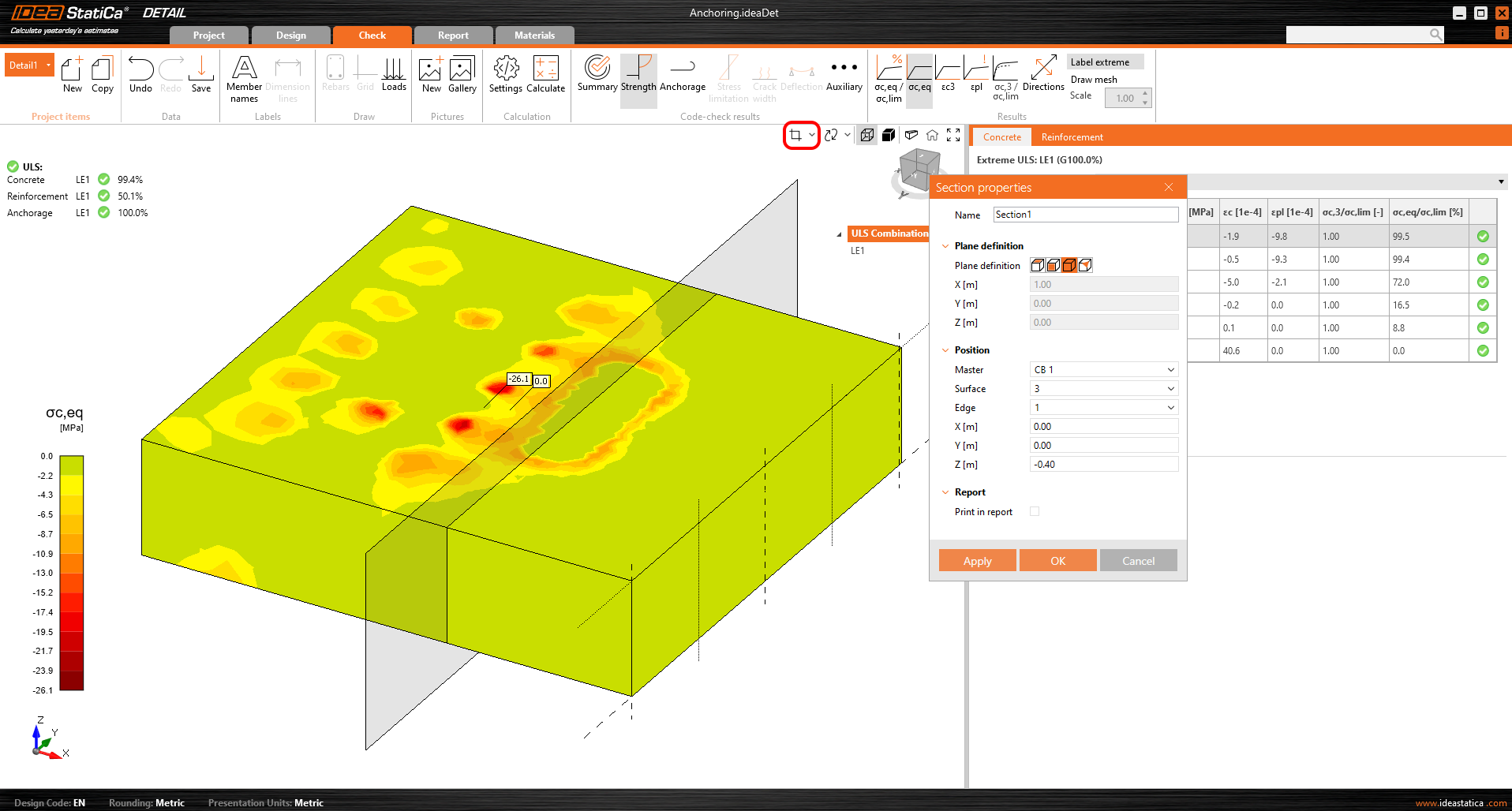
Then you can simply turn on the section button and the results will be displayed via a specified section.
Or there is an option to switch the view from 3D to 2D and for better clarity display the selected section in 2D.
Stress check
For a better understanding of the results and the theory implemented in the 3D Detail, the iconography has been significantly improved. In the "Strength" section, under the concrete stress assessment, you will find new icons and, most importantly, tooltips explaining the basic theory. These tooltips correspond to the theoretical background.
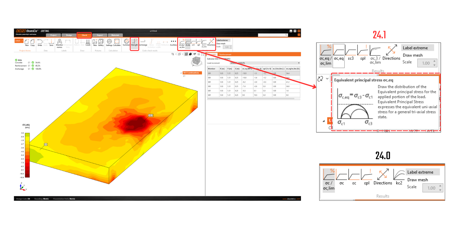
Released in IDEA StatiCa version 24.0.2
Try out the new features of IDEA StatiCa today
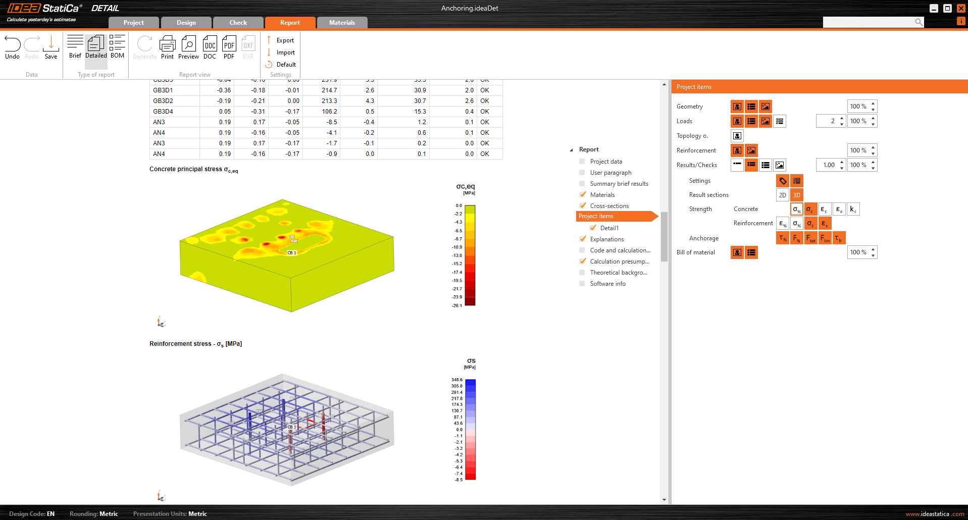
Report
As is standard in our applications, all results can be printed to an automatically generated report including Theoretical background, user paragraphs, and many more.